.ANS:

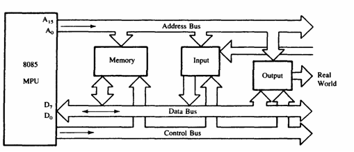
Above figure shows a simplified but formal structure of a microprocessor-based system or a product. Since a microcomputer is one among many microprocessor based systems, it will have the same structure as shown in Figure 3. It includes four components: microprocessor. input, output; and memory (Read/Write Memory and Read-Only Memory). These components are organized around .a common communication path called a bus. The entire group of components is also referred to as a system or a microcomputer system, and the components themselves are referred to as sub-systems. At the outset, it is necessary to differentiate between the terms microprocessor and microcomputer because of the common misuse of these terms in popular literature. The microprocessor is one component of the microcomputer. On the other hand, the microcomputer is a complete computer similar to any other computer, except that the CPU functions of the microcomputer are performed by the microprocessor. Similarly, the term peripheral ,is used for input/output devices. The various components of a microprocessor-based product or a microcomputer are shown in Figure and their functions are described in this section.
INPUT
The input section transfers data and instructions in binary from the outside world to the microprocessor. It includes such devices as a keyboard, a teletype, and an analog-to-digital converter. Typically, a microcomputer used in college laboratories includes either a hexadecimal keyboard or an ASCII keyboard as an input device. The hexadecimal (Hex) keyboard has 16 data keys (0 to 9 and A to F) and some additional function keys to perform such operations as storing data and. executing programs. The ASCII keyboard (explained in Section I .3) is similar to a typewriter keyboard, and it is used to enter programs in an English-like language. Although the ASCII keyboard is found in most microcomputers, single board microcomputers generally have Hex keyboards, and microprocessor-based products such as a microwave oven have decimal keyboards.
OUTPUT
The output section transfers data from the microprocessor to such output devices as light emitting diodes (LEDs), a cathode-ray tube (CRT), a printer, a magnetic tape, or another computer. Typically, single-board computers and rnicroprocessor based products (such as a dishwasher) include LEOs, seven-segment LEOs, and alphanumeric LED displays as output devices.
MEMORY
Memory stores such binary information as instructions and data, and provides that information to the microprocessor whenever necessary. To execute programs, the microprocessor reads instructions and data from memory and performs the computing operations in its ALU section. Results are either transferred to the output section for display or stored in memory for later use. The memory block shown in Figure 3 has two sections: Read-Only Memory (ROM) and Read! Write Memory (R/WM), popularly known as Random-Access Memory (RAM).
The ROM is used to store programs that do not need alterations. The monitor program of a single-board microcomputer is generally stored in the ROM. This program interprets the information entered through a keyboard and provides equivalent binary digits to the microprocessor. Programs stored in the ROM can only be read; they cannot be altered .
The Read/Write Memory (R/WM) is also known as user memory . It is used to store user programs and data. In single-board microcomputers, the monitor program monitors the Hex keys and stores those instructions and data in the R1W memory. The information stored in this memory can be easily read and altered.
SYSTEM BUS
The system bus is a communication path between the microprocessor and peripherals; it is nothing but a group of wires to carry bits. In fact, there are several buses in the system that will be discussed 10 the next chapter. All peripherals (and memory) share the same bus; however, the microprocessor communicates with only one peripheral at a time. the timing is .provided by the control unit of the microprocessor